.png?width=150&height=70&name=BWC%20Logo%20(Custom).png)
Aluminium Extrusions for Telecoms Engineering
Telecoms hardware is unforgiving: connector alignment, sealing performance, structural stability, and shielding continuity often have to work together, outdoors, for years, with little tolerance for variation.
Aluminium extrusion is a strong fit for telecoms engineering because it delivers repeatable section geometry over long lengths and lets you integrate mounting, alignment, gasket lands, cable channels, and functional rails into one profile. That typically means fewer parts, fewer tolerance stack-ups, faster assembly, and more consistent builds.
We support telecoms manufacturers with the full route, design-for-extrusion input, extrusion supply, CNC machining, finishing coordination, inspection focus, and packaging, so your housings and mounts fit, seal, and assemble reliably at production scale.

Telecoms extrusion: what “good” looks like
Telecoms assemblies often include multiple sensitive interfaces:
- Covers and gasket lands
- Connector faces and cut-outs
- Mounting faces and datums
- Bonding/earthing points
- Repeatable locating features for internal components
If a housing twists, the lid won’t seal. If datums drift, connectors won’t align. If contact faces vary, shielding performance can degrade.
Extrusion helps because it provides consistent geometry along the full length and allows you to design-in functional details instead of adding brackets, fabricated sub-parts, and secondary assemblies later.
Why aluminium extrusion works so well in telecoms
When extrusion is engineered early, you typically gain:
Repeatability over length
Ideal for enclosure sections, rails, carriers and modular formats where straightness/twist affects fit and sealing.
Feature integration that reduces parts
Design-in grooves, bosses, mounting lands, tracks, interlocks and internal ledges to reduce brackets, fixings and assembly steps.
Controlled interfaces where it matters
Build in defined geometry for lid/gasket lands, connector reference faces, and machining datums—then machine only the truly functional faces.
Efficient manufacturing route
Extrude the geometry cost-effectively, then apply CNC machining only where needed for interfaces, holes, slots, pockets and connector features.
Where aluminium extrusion adds value
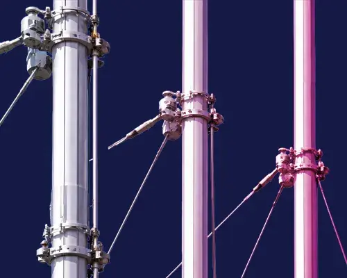
RF/EMI enclosures and interface stability
Aluminium is widely used in telecoms enclosures because it’s conductive, stable and suited to robust mechanical interfaces. Extrusion supports:
- consistent wall geometry
- repeatable seam design
- defined gasket lands
- controlled mating faces
Note: EMI/RF shielding performance depends on the full enclosure design (seams, apertures, bonding paths, gasketing, fasteners and assembly method).
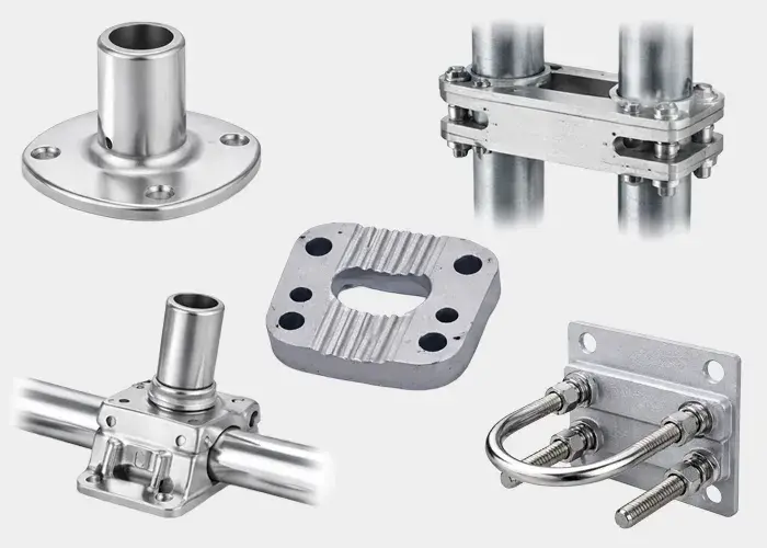
Mounting systems that build the same every time
Telecoms systems need “it fits every time” manufacturing. Extrusion is well-suited to:
- modular frames and carriers
- antenna support structures
mounting rails and equipment sub-assemblies
…especially when CNC machining is applied to the functional faces only
Outdoor durability for long-life assets
Telecoms equipment often lives outdoors. Aluminium’s corrosion resistance plus appropriate surface treatment (e.g., anodising or powder coating) supports long service life—when coating build-up and masking are planned around critical mating/locating surfaces.
Note: Coatings can reduce electrical contact. Where bonding/earthing is critical, define masked (uncoated) datum/contact faces or engineered bonding points.
Part-count reduction and simplified assembly
One of the biggest reliability and cost wins is replacing multi-part fabricated assemblies with a single extrusion (then machining where required):
- fewer interfaces
- fewer tolerance stack-ups
- fewer fixings
- fewer failure points in service
Tolerances & inspection: specify what matters (and avoid over-tolerancing)
A cost-effective tolerance strategy is to identify what is genuinely critical to function and keep non-critical geometry more open to improve yield and reduce cost.
We can help you:
- define machining and measurement datums
- tighten tolerances only on functional interfaces (alignment, sealing, contact/bonding areas)
- keep non-critical geometry more open to improve yield and reduce scrap
- specify straightness/twist only where assembly depends on it
- account for coating build-up where parts mate or locate
Once we know what has to align, seal, bond/earth, or mate, we can advise which dimensions should be controlled tightly and where general extrusion tolerances are appropriate.
Why BWC Profiles
You’re not just buying an extrusion, you’re buying a route to a part that assembles consistently.
- Design collaboration to achieve stable, extrudable profiles without losing function
- Support from prototype/samples through to repeat production
- Machining and finishing routes focused on the critical interfaces
- Practical advice on tolerance strategy, inspection focus, and cost drivers
- Supply support for consistent, repeatable delivery
We’ll come back with a practical extrusion + machining route and quote accordingly.

Aluminium Extrusions for Telecoms Engineering FAQs
Extrusion is well-suited to RF enclosures, modular housing sections, mounting rails, support frames, and profiles that need repeatable datums, sealing lands, and integrated mounting features—especially where long-length consistency matters.
Yes—aluminium is conductive and commonly used for telecoms enclosures. However, shielding performance depends on the full design: seams, apertures, gasket strategy, bonding paths, fasteners, and assembly method. Extrusion helps by enabling repeatable interface geometry.
Coatings can reduce electrical contact. If bonding/earthing is required, define masked (uncoated) contact faces or engineered bonding points so continuity is maintained where it matters.
Start by identifying what is truly functional: connector alignment faces, gasket lands, mating faces, and datums. Tighten tolerances there, and keep non-critical geometry more open. This typically improves yield and reduces cost.
Straightness/twist requirements should be set based on how the profile mates, seals, or locates in assembly. We’ll help you define what’s needed on the functional interfaces and avoid unnecessary constraints elsewhere.
Yes. We support machining such as drilling, tapping, slots, pockets, connector cut-outs, datum faces, and other functional features so you can receive parts ready for assembly.
A drawing (or concept) plus lengths, quantities, environment, finish requirement, and the critical functional dimensions (alignment, sealing/contact areas, connector faces, bonding points). Assembly notes help too.
Yes. Extrusion often allows you to integrate features that replace brackets, rails, and fabricated sub-assemblies—reducing part count and tolerance stack-ups.
A MUST-READ BLOG: Aluminium Extrusion Tolerances
Tolerances can make or break an aluminium extrusion and are key to precision engineering.
Learn what they mean and what drives variation in production. Understand standard vs tighter tolerances—and the trade-offs. Get practical tips to specify the right tolerance first time. Avoid rejects, delays, and costly rework.
